The Project
An extra deviation meter for on-site servicing can be quite useful and this project can provide most of the benefits of a commercial-grade instrument once calibrated.
This instrument is just an audio amplifier with a peak detector driving an analog meter calibrated in deviation. The audio input is taken from an el-cheapo radio scanner that can be picked up from a flea market for a few dollars. It needs to be able to cover the frequency range required to monitor.
Selecting a Suitable Scanner
As this instrument is to be used on amateur equipment it is necessary that it has an IF bandwidth sufficient that it can demodulate audio of at least 5kHz deviation, preferably more. This can checked by selecting a suitable RF frequency with a signal generator set for a level of say -110dBm and carefully sweeping it from the centre frequency to +/- 10kHz, noting at which point(s) the signal is muted. This must be greater than 5kHz, typically 7.5 for best results.
The Circuit
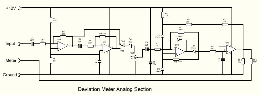
The audio is first buffered by an op-amp to prevent loading on the scanner, then via another op-amp as a switchable inverter, then to the peak detector. The detected output will be a DC voltage from 0v to rail volts depending on the audio input level and amplifier gain. The resultant DC output can then drive an analog meter of your choice via a SOT series resistor to limit the meter current.
Demodulator Output
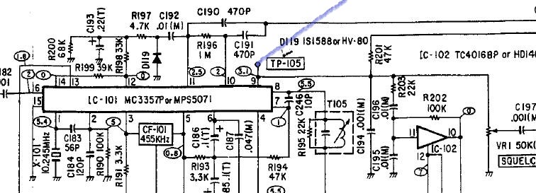
A typical scanner demodulator section
If the audio input is taken from the scanner it must be from the output of the IF detector chip (within the scanner), it cannot be from the later audio stage(s) as there most likely will be de-emphasis invoked and the audio will not be a true indication. Consult your scanner schematic to determine the right pin, usually pin9 on the demodulator chip in most scanners.
The Board Layout
The audio amp/detector was designed for VeroBoard and is easy to construct. The RED squares are the track cuts: make sure they are clean cuts by checking with a multi-meter.
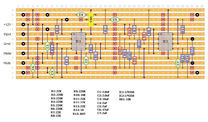
As the demodulated audio is low level it should be run in shielded wire, earthed one end only, return is via a separate ground wire. Power required is 12v at only a few milliamps and can be taken from the scanner.
Provision has been made to select positive and negative deviation swings with a simple SPST switch, the switchable inverter stage. This is most useful when checking modulation linearity.
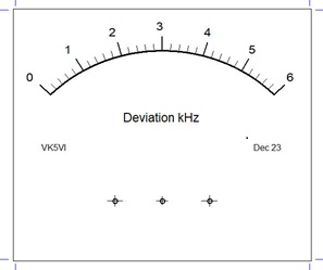
The Meter
A typical analog meter would be 0-1mA with the current limiting resistor R15 selected to provide FSD with a deviation of 5kHz and the gain control VR1 set for mid-range.
The meter scale is best made 0-6kHz to allow for adjustment up to and just past 5kHz for deviation linearity checking.
An excellent program from TonneSoftware is Meter which can provide a suitable scale for any analog meter, simply print the design on plain paper and paste over the original meter face..
The Meter program allows placement of text on the meter face.
Be aware that the free version only allows for 10x prints so be sure of your design before printing.
When designing a new meter face the program asks for a number of measurements and these are quite critical to get a good result.
The paid version is not expensive and allows unlimited prints.
Calibration
The first step in calibration is to start with the gain pot wound to minimum and with the scanner un-muted, then increase the gain level until a reading shows. Then adjust the gain for a half-scale reading.
The most difficult task is to calibrate the instrument accurately and for this a service monitor is required. However a work-around could be using a spectrum analyser function of a modern HF transceiver and simple signal generator could be a suitable substitute. Modulate the signal generator with a 1kHz tone, and monitor the spectrum display on the HF receiver.